What You Need To Know About Avionics System Testing

Home > Uncategorized

What You Need To Know About Avionics System Testing

What You Need To Know About Avionics System Testing

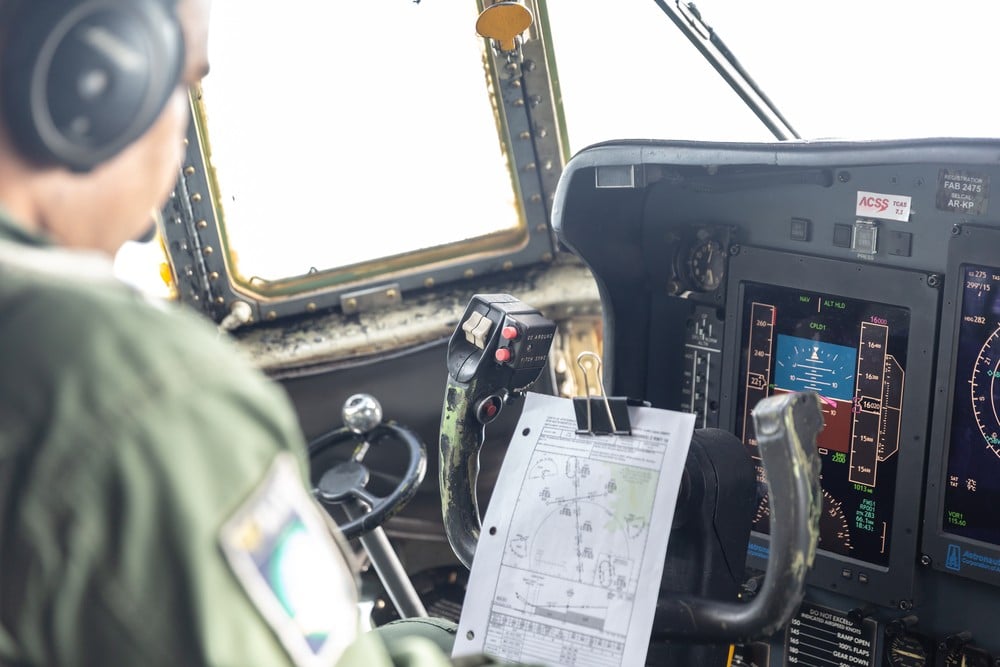
Avionics testing forms the backbone of ensuring flight safety and system reliability. This process involves rigorous evaluations to verify that avionics equipment functions correctly under various conditions. It’s not just about finding flaws; it’s about guaranteeing that every component can withstand real-world challenges, ensuring aircraft operate smoothly and securely.


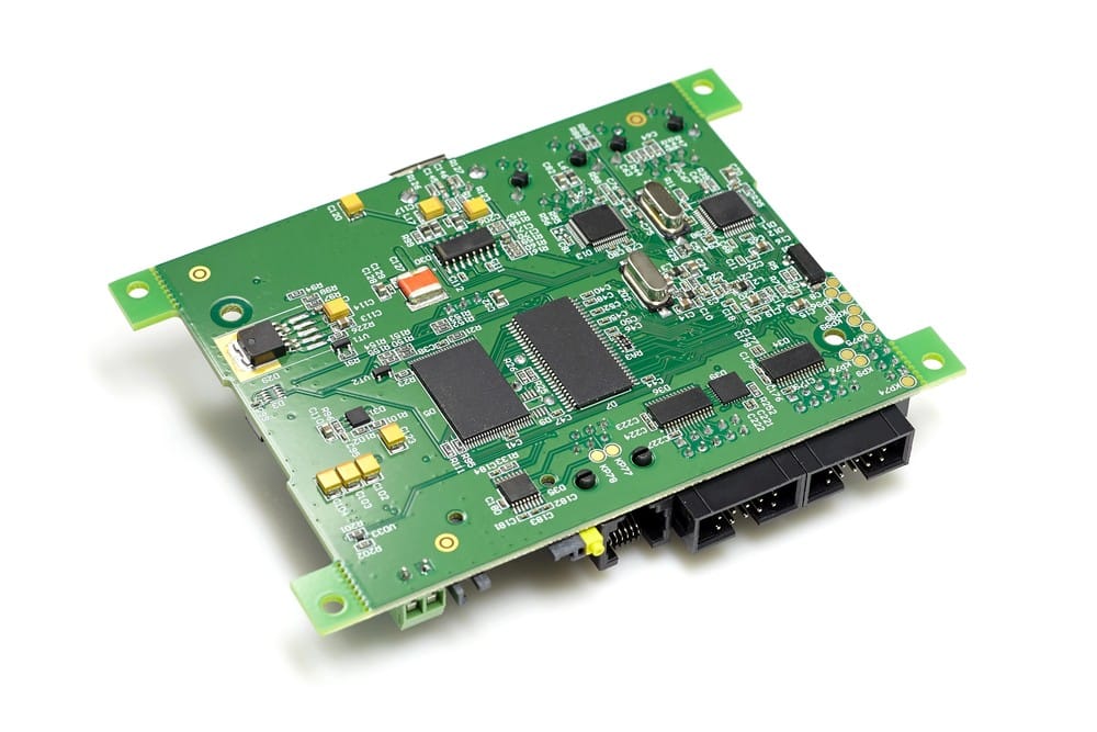
Sital Technology goes deep into the world of ARINC-429, bringing forth a suite of technologies that become the lifeline of avionics testing. Our Airborne Interface Cards and high reliability components leverage this protocol, making it simpler to simulate, analyze, and test avionics systems with unparalleled precision. This not only reduces the turnaround time for testing but also significantly enhances the dependability of avionics equipment.

The Crucial Role of Simulation in Avionics System Testing

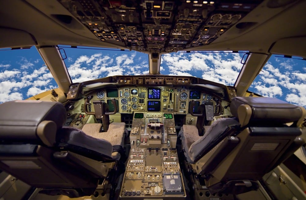
Simulation plays a fundamental role in avionics system testing by offering a safe and controlled environment to conduct tests that might be too risky or expensive to perform in real life. Through simulation, testers can recreate specific scenarios or conditions that an aircraft might encounter during its operations. This allows them to observe how the avionic systems perform under stress or failure without putting any actual aircraft at risk.


Such simulations also provide the opportunity to test systems at the limits of their operational parameters. By doing so, manufacturers can identify any potential weaknesses or failure points in a controlled setting, where they can make adjustments without real-world consequences. Apart from safety, simulation helps in cutting down the cost and time involved in testing, making it a preferred approach in the initial stages of avionics system verification.

Procedures and Process Involved in Avionics System Testing

The procedures and process involved in avionics system testing are meticulous and structured to cover all bases. This testing begins with individual components, ensuring each meets specific technical standards. It then progresses to integrated system testing, where the interaction between different avionic components is examined. This step is vital to ensure that all parts of the avionic system communicate and function together as intended.


Testers employ various tools and technologies during these procedures, from software that simulates flight conditions to hardware that replicates aircraft inputs and outputs. This thorough testing process is vital to detect any errors or issues that might impede the avionic systems’ performance or reliability. By identifying and addressing these issues early, companies can avoid costly downtime or, more importantly, prevent potential safety hazards.

Importance of Regulatory Compliance in Avionics System Testing

Regulatory compliance emerges as a cornerstone in avionics system testing, embodying a set of standards and requirements set by aviation authorities. These regulations ensure that avionic systems adhere to the highest safety and performance standards, protecting passengers and crew alike. Companies must navigate through these regulatory waters carefully, as non-compliance can lead to severe repercussions, including fines, grounding of aircraft, or in worst-case scenarios, revocation of operating licenses.


Remaining compliant involves staying updated with any changes or updates in the aviation regulations and incorporating these into the testing process. This ensures that the avionic systems not only meet the current industry standards but are also prepared for future advancements or regulatory adjustments. Thus, regulatory compliance is not just about adhering to requirements; it’s also about ensuring a commitment to safety and quality in the aviation industry.

Challenges and Solutions in Modern Avionics System Testing

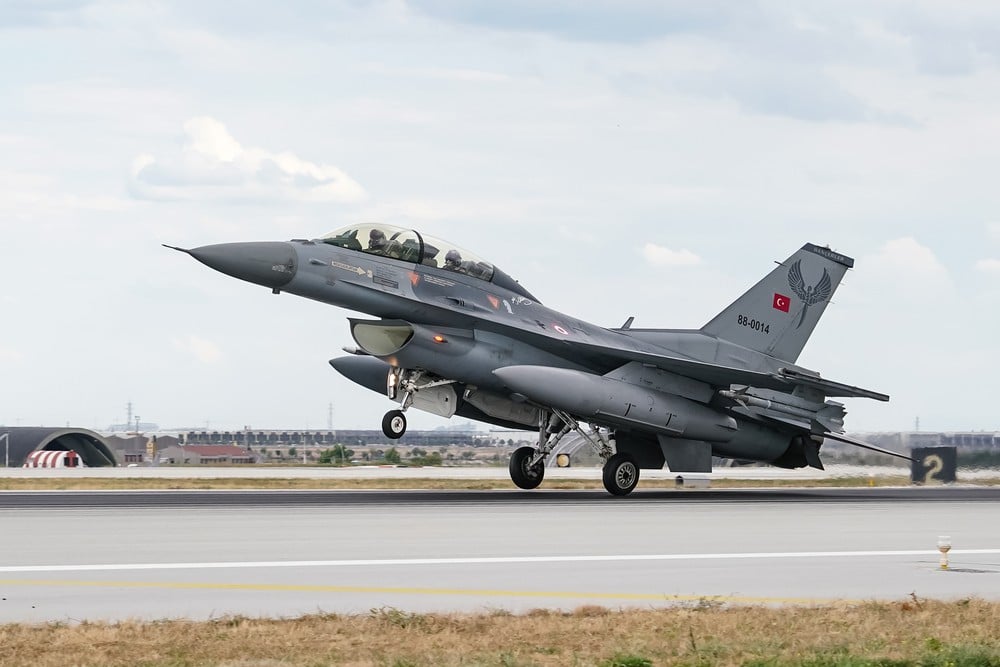
Testing modern avionics systems presents unique challenges. The increasing complexity of these systems, integrated with advanced software and hardware, demands rigorous and more sophisticated testing methods. One of the main hurdles is the need to test these systems in a range of environmental conditions they’ll encounter in actual operation, which may be difficult to replicate reliably on the ground.


Solutions to these testing challenges are as innovative as the systems themselves. Advanced simulation tools are being developed to better imitate a wide array of flight conditions. Another approach involves modular testing; breaking down the system into smaller, more manageable units for individual assessment before integrating and testing them as a whole.

Safety Measures and Precautions in Avionics System Testing

Safety is the bedrock of avionics system testing. Industry professionals continually update safety measures and precautions to mitigate risks. One key approach is redundancy; incorporating multiple fail-safes within the system to ensure that if one component fails, others can take over to maintain operations until the issue is rectified.


Testing teams place great emphasis on minimizing hazards. This includes routine checks of test equipment, adherence to safety protocols, and training teams to handle emergency scenarios. Precautionary measures, like using inert equipment that simulates operational load without the risk, are becoming standard practice.


Strict guidelines and checkpoints are established to ensure that each phase of the testing process is completed with adherence to safety standards. These guidelines help in systematically identifying and resolving any potential risks before they escalate into significant problems. By doing so, the focus on safety remains unyielded throughout the testing process.

Impact of Avionics System Testing on Aircraft Performance

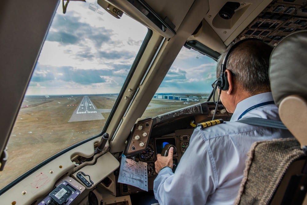
Avionics system testing has a direct and significant impact on aircraft performance. By meticulously examining every component and system, testing ensures that each part operates at its peak, which in turn, optimizes the overall performance of the aircraft. This level of performance is not just about speed or fuel efficiency; it encompasses reliability, safety, and passenger comfort.


The feedback from system testing often leads to design enhancements. These changes are aimed at minimizing resistance, improving navigation accuracy, and enhancing communication fidelity. The ultimate goal is an aircraft that operates smoothly, offering a better experience for both the crew and passengers.

Equip Your Testing Arsenal with Avionics Testing Equipment

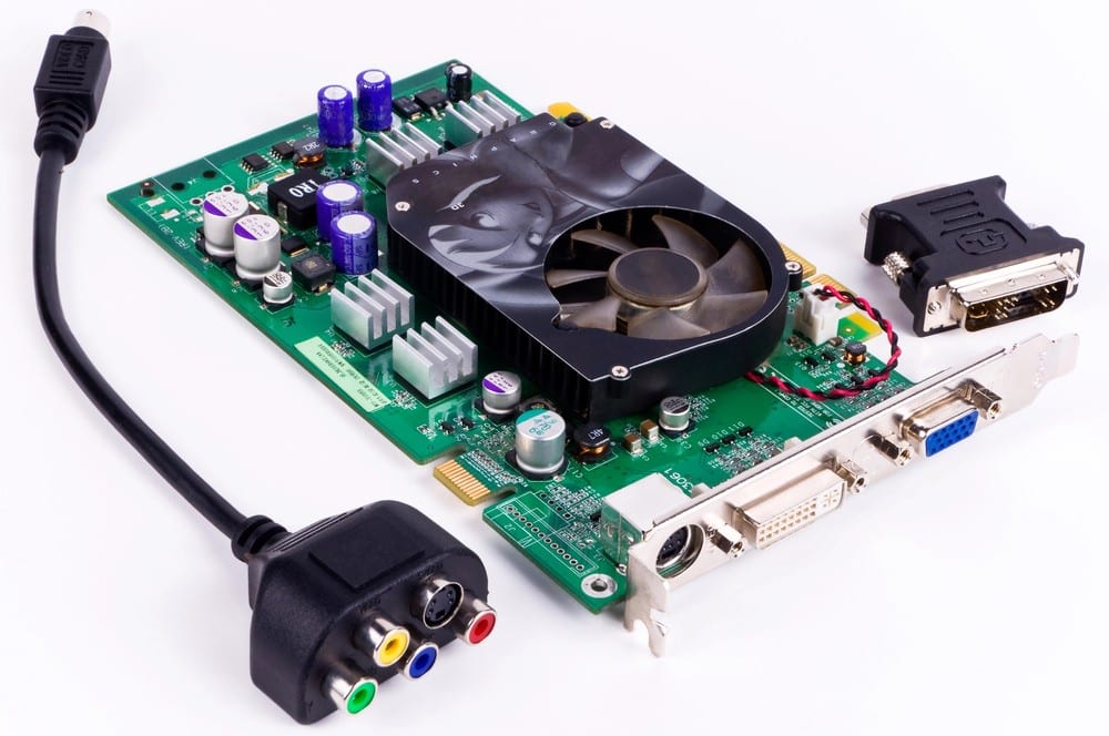
Stepping beyond protocols to the world of physical testing, our avionics testing equipment emerges as a crucial ally. From comprehensive testers to bespoke IP cores tailored for MIL-STD-1553, EBR-1553, and beyond, our equipment is built to tackle the complexities of modern avionics systems. Whether it’s aerospace, automotive, or space-grade applications, our solutions ensure that your systems meet the highest standards of reliability and safety.


Our cutting-edge avionics testing solutions are designed not just to meet but to exceed industry standards. Reach out today and elevate your avionics systems to the zenith of efficiency and reliability.

The Significance Of ARINC-429 In Today’s Aviation Technology

The Significance Of ARINC-429 In Today's Aviation Technology

In the high-stakes domain of aviation technology, ARINC-429 holds an irreplaceable position. This data bus standard allows different systems and components within an aircraft or between the aircraft and ground stations to communicate with each other. With a high degree of accuracy, speed, and reliability, it forms the very backbone of communication, ensuring safety and efficiency.


At Sital Technology, we’ve made it our aim to refine and elevate the ARINC-429 solutions your operations depend on daily. We design and manufacture cutting-edge products like Airborne Interface Cards and High-Reliability Components, all built around ARINC-429. These components are integral in enabling accurate data transfer between different systems, significantly enhancing the reliability and efficiency of your operations.

Ensuring Robust Data Communication with ARINC-429 in Aviation

Aviation safety and efficiency hinge on the flawless exchange of data between various systems onboard an aircraft. ARINC-429 facilitates this by offering a common language for avionics components. Unlike other communication protocols that may vary in form and function, ARINC-429 provides a standardized method, ensuring that critical information is reliably transmitted and received, regardless of the complexity or variety of systems involved. This uniformity is key to preventing errors that could arise from miscommunication, thus upholding the stringent safety standards required in aviation.


What makes ARINC-429 stand out is its simplicity and reliability. It uses a single-source, point-to-point data transmission method, which minimizes the likelihood of data collisions and loss. This ensures that important flight commands and status information are conveyed accurately from one system to another, supporting vital functions such as navigation, flight control, and engine monitoring.

Advantages of Standardization by Adopting ARINC-429 in Aviation

Adopting ARINC-429 brings uniformity across different avionics systems, significantly reducing the complexity of system integration. This standardization simplifies the design and maintenance of avionics, as engineers and technicians deal with a consistent set of protocols. As a result, the time and resources spent on training staff are considerably lower, while the potential for human error is reduced.


Moreover, the widespread use of ARINC-429 eases the process of upgrading existing systems or integrating new ones. Compatibility issues become less of a concern, as ARINC-429 serves as a common foundation upon which various systems can reliably interact. This not only accelerates the development of innovative avionics solutions but also extends the lifespan of aircraft by ensuring that they can be updated efficiently to meet evolving operational requirements.

Boosting Aircraft Performance through ARINC-429 Enabled Systems

ARINC-429 does more than just facilitate communication between avionics systems; it directly contributes to the enhancement of aircraft performance. By ensuring the precise and timely exchange of data, this standard supports optimized flight paths, better fuel efficiency, and improved overall system reliability. Pilots benefit from having accurate, up-to-date information at their fingertips, allowing for more informed decision-making that enhances flight safety and efficiency.


Furthermore, ARINC-429 supports the implementation of advanced automation features in modern aircraft. These systems rely on the seamless flow of data to perform complex tasks, from autopilot operations to sophisticated diagnostics checks. ARINC-429’s dependable communication framework is vital in enabling these technologies, which in turn, elevate the capabilities and performance of the aircraft.

ARINC-429 Facilitating Enhanced Safety Measures on Aircraft

The ARINC-429 standard plays a considerable role in bolstering safety. By offering a dependable protocol for system-to-system communication, it ensures critical avionics functions interact without error. Such reliability is fundamental to maintaining safety in the skies. Each data transmission adheres to stringent guidelines, thereby minimizing opportunities for the transmission errors that could potentially lead to unsafe situations.


Certainty instilled by ARINC-429’s consistency supports pilot awareness. As pilots receive coherent and accurate data, they can trust the instruments to reflect the aircraft’s real-time status accurately. This clarity is paramount during critical phases of flight and when responding to unforeseen circumstances. Quick and correct decisions often depend on the integrity of data an aircraft’s systems provide.

ARINC-429’s Contribution to Real-Time Information Sharing in Aircraft

Immediate access to flight data can define the success of a mission or flight. ARINC-429 enhances this data’s flow, allowing systems to share updates without delay. This fast response is critical during emergency situations where seconds matter. Reliable communication ensures that flight crews and automated systems get timely data to adjust to changing flight conditions or system statuses.


This consistent flow of information enables in-flight systems to operate with a coherent understanding of the aircraft’s situation. As a result, pilots are better equipped to handle changing flight dynamics, maintain aircraft stability, and ensure passenger comfort. Such efficient information sharing under ARINC-429’s standard protocols is elemental in the practical management and operation of modern aircraft.

Enhancing Diagnostics and Maintenance with ARINC-429 Protocol

By establishing a uniform method for sending and receiving system data, ARINC-429 simplifies the detection and interpretation of avionics issues. This has a profound impact on diagnostic processes. Maintenance crews can readily access and analyze data from various systems, making targeted diagnostics faster and more effective.


This protocol also paves the path for proactive maintenance strategies. With data readily available in a consistent format, it becomes easier to predict potential failures before they occur, leading to preemptive maintenance and less unexpected downtime. A proactive approach not only extends the lifetime of avionics components but also maintains the high levels of aircraft availability and safety that are imperative in aviation operations.


Lastly, ARINC-429 aids in the recording of flight data for later analysis. Such detailed records are essential for post-flight checks and for investigations following any incidents. The capability to review unambiguous data about an aircraft’s systems and performance during a previous flight is a powerful tool for maintaining high safety standards and improving future operations.

Pioneering Communication Technologies and Solutions

Beyond offering communication technologies and solutions centered around ARINC-429, we also provide products for MIL-STD-1553, EBR-1553, ARINC-825, CAN, and Space Grade applications. Sital Technology guarantees flexible, reliable, and accurate solutions adaptable to every need, ensuring you have the technology to support even the most complex communication and data sharing requirements.


With our advanced solutions, we can help you navigate the complexities of modern aviation technology and stand out in the fast-evolving industry. Connect with Sital Technology today and witness how we can transform your communication capabilities for a brighter and safer tomorrow.

The Complete Guide To CAN Bus Connectivity: Connector And Cable Considerations

The Complete Guide To CAN Bus Connectivity Connector And Cable Considerations

Choosing the right CAN bus connector is a critical step for anyone looking to establish or improve vehicle communication networks. This connector isn’t just a piece; it’s the gateway ensuring clear, uninterrupted data flow across the various parts of a vehicle’s system. The proper selection affects everything from the network’s reliability to its overall performance, making knowledge in this area invaluable.


Sital Technology takes pride in offering leading-edge automotive databus solutions. Our solutions cater specifically to aerospace, avionics, and automotive professionals, ensuring their systems use the most effective CAN bus connectors and cables. We aid our clients in achieving seamless and fault-tolerant communication within their vehicles’ networks, maximizing performance and durability.

Selecting the Ideal Cable Length for CAN Bus Connectivity

Deciding on the length of your CAN bus cables is more than a measure of distance; it directly influences the efficiency of data transmission. A cable that’s too long may lead to a delay in communication, whereas one that’s too short might not reach all the necessary components. What’s needed is a balanced approach.


A longer cable may seem like a safe bet for future expansion but bear in mind it could introduce latency. Each segment must be just long enough to connect the nodes without excess slack. It’s about finding that sweet spot where communication is unimpeded by unnecessary cable length.

Avoiding Signal Degradation by Considering CAN Bus Cable Type

Cable type matters considerably in CAN bus systems. Shielding, thickness, and material quality can vastly affect signal clarity. An inferior cable might cause signal loss or electromagnetic interference, which is not an option where precision is pivotal.


A shielded cable ensures signals remain intact even in areas with high electronic noise. It’s a safeguard against external interference, making it an indispensable choice. Yet, not all shielding is equal. Aim for a cable that provides robust protection without becoming stiff or unwieldy—flexibility matters for installation and maintenance.


The next layer to consider is the conductor itself. High-quality materials transmit signals without degradation over distances, critical for maintaining the integrity of the communication. It pays to invest in cables that promise longevity and consistent performance even under the duress of high-speed data transfer.

Ensuring Proper Connector Alignment for Optimum CAN Bus Performance

Connectors serve as the critical link in your CAN bus system. A misaligned or poorly fitted connector is a silent killer in data communication. It’s imperative that each connector fits snugly and securely, ensuring a stable connection that won’t falter under stress.


The installation should not be rushed. Proper alignment requires a steady hand and a keen eye. Each pin and socket must meet precisely, with no room for error. The connector should lock into place with confidence, signaling a secure bond.


Regular checks are non-negotiable. Vibration and wear can compromise connections over time, and detecting issues early keeps the system operational. A best practice is to integrate routine maintenance into the workflow, where connectors are inspected for signs of stress or damage.

Protecting Your Systems with CAN Bus Connector Housing Material

The housing material of your CAN bus connectors plays a vital role in both protecting your system and ensuring long-term reliability. What you choose as a shield can make the difference between a system that endures and one that falters under environmental stress.


Metals like aluminum and stainless steel are popular for their durability and resistance to corrosion. These materials guard against harsh conditions, including extreme temperatures and moisture, which might otherwise compromise the integrity of your connections. Opting for rugged materials ensures your system remains safe even in demanding environments.


However, it’s not just about withstanding the elements. The electromagnetic interference (EMI) protection offered by certain metals can safeguard your data transfer from noise, ensuring uninterrupted communication. This blend of physical and signal protection makes choosing the right housing material an exercise in balancing priorities for peak system performance.

Defining Cable Termination Requirements for Effective CAN Bus Connectivity

The way you terminate your CAN bus cables is not merely a procedural step; it’s a critical aspect of establishing effective connectivity. Proper termination prevents signal reflections that can disrupt communication, making it imperative to adhere to precise requirements.


Termination resistors play a central role in this context. Placing a resistor at each end of the bus cable ensures that signals are properly absorbed, preventing them from bouncing back and forth along the cable. The value of these resistors, typically around 120 ohms, is chosen to match the impedance of the cable, balancing the system.


The placement of termination points also requires attention. They should be located at the extremes of the network to encompass all communication within a bounded environment. This strategic positioning maximizes the effectiveness of the termination, ensuring a stable and reliable data transfer.


It is worth noting that while termination is vital for network integrity, over-termination can lead to signal attenuation. Striking the right balance is key. It often requires a detailed analysis of the network’s layout and the electrical characteristics of the system, underscoring the importance of precision in every step of the connectivity process.

Prioritizing Signal Integrity Through Cable Gauge Selection for CAN Bus

Choosing the right cable gauge is essential for maintaining signal integrity in CAN bus systems. This decision impacts the resistance of the cable, which in turn, affects both the quality and speed of data transmission. A thinner cable might be more flexible and easier to route, but it can also introduce greater resistance and potential signal degradation.


For longer distances, a thicker gauge cable is often necessary to minimize resistance and maintain signal clarity. This ensures that data can travel swiftly and accurately across the network without loss or distortion. Yet, the choice of gauge must also consider the environment and space constraints, balancing performance needs with practical installation requirements.

Advancing Your Projects with Our CAN Bus Technology

Our commitment to excellence goes beyond basic connectors and cables. We understand that the backbone of any vehicle’s databus system lies in the intricacies of CAN bus technology. Sital Technology’s tailor-made solutions, including Airborne Interface Cards and bespoke IP cores, support our clients in harnessing the full potential of CAN bus systems, providing reliable and scalable network communications.

The Advantages Of MIL-STD-1553 In Military Operations

The Advantages Of MIL-STD-1553 In Military Operations

MIL-STD-1553 has set the standard for reliability in military digital communication, ensuring seamless, error-free data exchange. This robust framework facilitates the integration of weapons, radars, and other critical systems, significantly enhancing military operations’ efficacy and strategic capability.


The adaptability and reliability of MIL-STD-1553 not only boost operational performance and serve as a vital link in the command-and-control chain, ensuring that complex information is accurately and swiftly conveyed.


Sital Technology specializes in providing advanced DataBus communication technologies and solutions tailored specifically for the avionics, aerospace, and automotive sectors. Our MIL-STD-1553 solutions are at the heart of our offerings.


We deliver Airborne Interface Cards, Testers, High-Reliability Components, and customized IP cores designed to meet the rigorous demands of MIL-STD-1553, EBR-1553, ARINC-429, ARINC-825, CAN, and Space Grade applications. Our solutions are engineered to elevate the operational efficiency of your projects, enhancing system integration and reliability.

MIL-STD-1553 Increases System Reliability in Harsh Military Environments

The robustness of MIL-STD-1553 is evident in its ability to maintain consistent communication under extreme conditions. This standard is designed with hardiness in mind, guaranteeing that data transfer is not only swift but also uninterrupted, regardless of external factors. Such reliability is paramount in military operations where the cost of communication failure can be exceptionally high.


The architecture of MIL-STD-1553 is such that it supports redundant pathways for data transmission. This means that if one path encounters a problem, the system automatically reroutes the data, thus maintaining a steady flow of information. This redundancy is a critical feature, ensuring that operations can continue smoothly without significant delays or data loss.


Moreover, the consistent improvement of MIL-STD-1553 test equipment has played a substantial role in enhancing system reliability. These advancements enable early detection and resolution of potential issues before they escalate, further bolstering the standard’s robustness in challenging environments.

Enhancing Data Security Through MIL-STD-1553’s Built-In Encryption Features

Data security is a paramount concern for military operations, where the risk of sensitive information falling into the wrong hands can have dire consequences. MIL-STD-1553 addresses this concern with integrated encryption capabilities, ensuring that data remains protected throughout its transmission.


The encryption features of MIL-STD-1553 are sophisticated, yet they operate seamlessly within the system, adding an essential layer of security without compromising the speed or efficiency of data transfer. This ensures that even if data interception occurs, the information remains inaccessible to unauthorized parties.


The standard also supports the implementation of various encryption algorithms, allowing organizations to choose the best option that suits their specific security needs. This flexibility is invaluable, given the evolving nature of cyber threats and the need for military operations to stay one step ahead.

Streamlining Communication Among Diverse Military Equipment with MIL-STD-1553

One of the standout benefits of MIL-STD-1553 is its ability to facilitate cohesive communication between different types of military equipment. This interoperability is crucial for the integrated operations that define modern military strategy.


MIL-STD-1553 standardizes the communication protocol, ensuring that all devices, regardless of manufacturer, can exchange data smoothly. This uniform approach eliminates compatibility issues that can otherwise arise, streamlining the integration of new technologies into existing systems.


Furthermore, the standard simplifies the development process for new military equipment. Manufacturers can design their products with the assurance that they will operate harmoniously within the MIL-STD-1553 ecosystem, allowing for quicker deployment and reduced costs.

Ensuring Real-Time Data Exchange Accuracy in Mission-Critical Operations

Accuracy in data transmission is vital in mission-critical military operations, where decisions depend on the reliable exchange of information. MIL-STD-1553 ensures precision in communication, enabling real-time operational performance. This high level of accuracy is achieved through rigorous protocol specifications, which mandate exact timing and data formatting.


With MIL-STD-1553, messages are delivered within a predictable timeframe, which is indispensable for applications requiring synchronized timing. The standard’s sophisticated error-checking mechanisms detect and correct any anomalies, preserving data integrity. This process minimizes the risk of misinterpretation or delays in command execution, contributing to successful mission outcomes.


For military operations, the consequences of inaccurate data can be significant. MIL-STD-1553 addresses this by providing a stable, dependable platform where each piece of data can be trusted. This trust is the backbone of coordinated efforts across multiple systems and is a testament to the standard’s value.

MIL-STD-1553 Facilitates Efficient Multiple Device Integration and Control

The integration of multiple devices within military systems can be daunting, but MIL-STD-1553 simplifies this process. By offering a common communication standard, it allows for the efficient management and control of various devices. This enables seamless interaction between components that need to work in harmony for operational efficiency.


With its clear-cut message formats and communication protocols, MIL-STD-1553 facilitates the addition and integration of new devices without the need for extensive customization. This plug-and-play functionality saves time and reduces the risk of errors during system upgrades or expansions.


The use of this standard provides operators with a central point of control. With every device speaking the same ‘language,’ the complexity of managing a diverse array of technologies is significantly reduced. This centralized control leads to better coordination, quicker responses, and a more cohesive operation of military systems.

Reducing System Complexity and Maintenance Costs with MIL-STD-1553 Standards

MIL-STD-1553 has a profound impact on the simplification of system architectures. The standard’s streamlined approach to data bus design reduces the need for multiple wires and connections necessary in complex systems. This simplification plays a significant role in enhancing system durability and reliability, while also making maintenance tasks more manageable.


The cost of system upkeep is a critical consideration, and MIL-STD-1553 helps in this regard by decreasing the need for frequent overhauls. Its robust design means less wear and tear on components and a longer operational life for the overall system. This longevity translates into lower replacement and repair expenses over time.

Your Trusted Partner for a Reliable MIL-STD-1553 System

Sital Technology stands as your ideal partner for integrating a MIL-STD-1553 system into your aerospace, avionics, or automotive projects. Our dedication to innovation, combined with our extensive range of high-quality components and bespoke IP cores, ensures that your systems communicate efficiently and reliably under any circumstances. Our team of experts is committed to providing you with the cutting-edge solutions needed to stay ahead in the fast-paced aerospace, avionics, and automotive technology industries.


Our proven expertise in MIL-STD-1553 solutions is your gateway to integrating the most advanced and reliable communication technologies into your operations. Contact us, and let’s work together to bring your projects to new heights.

In-Depth Analysis: ARINC-629 Vs. ARINC-429 In Aviation Systems

In-Depth Analysis ARINC-629 Vs. ARINC-429 In Aviation Systems

The arena of aviation communication technology stands witness to a significant ARINC 629 vs ARINC 429 evolution – the transition from ARINC 429 to ARINC 629. Originally, ARINC 429 marked a milestone, establishing a standard for point-to-point data exchange that has been integral to the aviation industry. It’s known for its reliability and precision, ensuring that critical flight data reaches its destination without error.


On the other hand, ARINC 629 represents a step forward, embracing a more inclusive communication protocol that allows multiple systems to talk to each other simultaneously, enhancing the aircraft’s operational capabilities.


Sital Technology emerges as a frontrunner in providing top-tier ARINC-429 solutions. Our catalog, featuring everything from sophisticated Airborne Interface Cards to bespoke IP cores, ensures your systems communicate flawlessly under the ARINC 429 standard. We pride ourselves on delivering solutions that not only meet but exceed the demands of avionics, aerospace, and automotive sectors in terms of reliability and efficiency.

The Evolution from ARINC-429 to ARINC-629 in Aviation

ARINC 429 set the stage by offering a reliable protocol for point-to-point communication. Its simplicity made it widely adopted, laying a robust foundation for avionics systems in numerous aircraft. However, as the complexity of avionics systems grew, the need for a more advanced standard became apparent. This led to the development of ARINC 629, which offered significant enhancements. Unlike its predecessor, ARINC 629 supports multi-transmitter and receiver environments, allowing for a higher degree of flexibility and efficiency in data exchange.


The fundamental shift from a point-to-point to a multi-point communication model underscores the evolution from ARINC 429 to ARINC 629. This transition not only reflects the growing demands of modern aviation but also the industry’s commitment to adopting technologies that improve performance and safety.

Data Transfer Speeds ARINC-629 VS. ARINC-429 Comparison

When comparing ARINC 629 and ARINC 429, one of the most significant differences lies in their data transfer speeds. ARINC 429 operates at a maximum speed of 100 kilobits per second, which was adequate when the standard was introduced. However, ARINC 629 brings a substantial increase, capable of data transfer speeds up to 2 megabits per second. This leap in speed addresses the escalating data requirements of contemporary avionics systems, enabling faster and more efficient communication between components.


This improvement is not just a matter of numbers. The higher data transfer rate of ARINC 629 facilitates real-time sharing and processing of critical flight and system information. It ensures that modern aircraft, equipped with an array of complex systems, can exchange data swiftly, enhancing overall system responsiveness and reliability.

The Network Topology Differences Between ARINC-629 and ARINC-429

Understanding the network topology differences between ARINC 629 and ARINC 429 is essential for grasping how data communication has evolved. ARINC 429 employs a simple, straightforward approach where each connection is made point-to-point, limiting the configuration to one transmitter and one receiver. This makes the system easy to understand but relatively inflexible and limited in scalability.


In contrast, ARINC 629 adopts a bus network topology, allowing multiple devices to communicate over a single data bus. This configuration dramatically increases the network’s flexibility and scalability. It permits a more complex integration of systems and sensors, facilitating a collaborative information exchange environment. This ability to connect multiple transmitters and receivers over the same bus without sacrificing data integrity or speed is a testament to the technological advances achieved with ARINC 629.

The Impact of ARINC-629 on Aircraft System Integration

The progression from ARINC 429 to ARINC 629 signifies more than just the evolution of DataBus communication technologies. It marks a transformation in the approach to aircraft system integration. Inherent in the design of ARINC 629 is the enhanced ability to connect multiple systems and devices – a far cry from the independent, isolated systems that were prevalent during the reign of ARINC 429.


ARINC 629 allows multiple transmitters and receivers to function on the same data bus. This breakthrough ended the significant restrictions imposed by the point-to-point connectivity of ARINC 429. The flexibility and scalability inherent in ARINC 629 accelerated integration of complex aircraft systems willing to work together for flight management, safety, and passenger entertainment.


The increased ability to integrate disparate systems under ARINC 629 has been a stepping stone in the advancement of more sophisticated aircraft designs. It has fallen in perfectly with the functioning of modern aircraft whose systems often need to communicate with multiple other systems in real-time.

Data Capacity and Efficiency in ARINC-629 and ARINC-429

With ARINC 629 came a substantial leap in data capacity, a clear progression from ARINC 429, which was limited by a maximum data rate of 100 kilobits per second. ARINC 629 offers a whopping 2 megabits per second, a significant factor in handling the escalating data needs of modern avionics.


This improved data capacity links directly to increased efficiency. The high-speed data transfer capability of ARINC 629 means systems can exchange large volumes of information swiftly. It reduces delays, mitigates the risk of data bottlenecks, and contributes to improved performance and safety.

Reliability Factors of ARINC-629 and ARINC-429 Protocols

Reliability is paramount in aviation communication technologies and protocols. Both ARINC 429 and ARINC 629 provide a robust and reliable framework for data transfer among avionics systems. Each brings its unique attributes to the table, contributing to the reliability of aircraft operations.


ARINC 429’s point-to-point approach ensures a secure and dependable connection between two systems. This protocol’s simplicity makes it exceptionally reliable, as there are fewer components to fail, and the data path is straightforward.


In contrast, ARINC 629’s multi-transmitter and receiver model introduces more complexity. Yet it manages to maintain high reliability levels. It accomplishes this with a redundancy feature which ensures that multiple devices can send the same data. If one transmitter fails, other devices can continue operating and sending the necessary data, thereby preventing critical information loss.

Leading the Way with ARINC-429 Interface Products

Continuing our commitment to innovation, we extend our expertise to ARINC-429 interface products. Designed with precision to ensure seamless integration and superior performance, our products are the backbone of effective data bus communication in aviation systems. Whether it’s MIL-STD-1553, EBR-1553, or Space Grade applications, our offerings are tailored to propel your communication technologies to the forefront of industry standards.


Connect with us and discover how we can transform your communication capabilities into a model of aviation excellence.

How To Wire A CAN Bus: Expert Tips For A Smooth Installation

How To Wire A CAN Bus Expert Tips For A Smooth Installation

The complexity of CAN Bus wiring unfolds when building a robust network for high-functioning vehicle systems. Every connection made can transform the efficiency of communication lines within automotive, aerospace, and avionics sectors.


While exploring CAN Bus and ARINC-825 technology, Sital Technology emerges as an indispensable companion. We harness the convergence of these systems to offer cutting-edge solutions designed for seamless integration. This perfect sync drives the power of advanced vehicle data networks.

Selecting Appropriate Cable Types for Reliable CAN Bus Communication

The cables you choose for CAN Bus systems are more than just physical connections; they are the lifelines that carry critical information. To ensure reliable communication, selecting the right type of cable is paramount. The environment in which the cables will operate is a decisive factor. For instance, cables used in high-temperature areas of an aircraft must withstand significant stress without losing performance.


Additionally, the flexibility of the cable is fundamental. Wiring in automobiles, where space is at a premium, requires cables that bend without breaking, maintaining integrity while conforming to the spaces available. The idea is to choose a cable that does not compromise on flexibility, durability, or performance.


But the robustness of a cable is about more than just the immediate environment. It must also resist electronic interference that can disrupt signals. A cable with adequate shielding counters possible noise form surrounding electronics, ensuring that the communication on your CAN Bus network remains clear and uninterrupted.

Ensuring Correct Terminal Resistance for Optimizing CAN Bus Performance

Terminal resistance in CAN Bus wiring isn’t just another specification; it’s a cornerstone of system performance. The ideal resistance ensures signals are pristine by the time they reach their destination. A common benchmark is 120 ohms, balancing cable impedance across the network and keeping reflections to a minimum.


The placement of these resistors can affect performance. Each end of the network harbors a resistor, ensuring signals don’t echo back into the system. This careful consideration keeps the data flowing smoothly, a prime concern where a split-second delay can mean the difference between routine operations and system failures.


Balancing resistance is an art; too much of it and your signals weaken. Too little and the network becomes susceptible to noise. Crafting an environment where resistors work harmoniously requires precision, a deep understanding of the network’s design, and an appreciation for the collaboration between hardware components.

Master the Art of Proper Cable Shielding in CAN Bus Wiring

Cable shielding in CAN Bus wiring is akin to an art form. More than just wrapping a cable, it’s about ensuring the integrity of the data being transferred. Like a guarded fortress, shielding protects the signal within from the electronic disturbances that rage outside.


Choosing a shield entail understanding potential interferences. The humming electronics of a car or the dynamic environment of an aircraft are teeming with electronic noise which can invade and corrupt communication. Your shield must rise to this challenge, providing sanctuary for the delicate signals within.


Yet, a shield is not simply a barrier; it must balance protection with flexibility. Cables must navigate the tight confines and bends of machines and vehicles. The right shielding bends without breaking, integrates without adding undue weight, and protects without compromise.

Utilize Twisted-Pair Cables for Minimizing Interference in CAN Bus Networks

Twisted-pair cables are a smart choice for reducing interference in CAN Bus systems. By intertwining the wires, these cables naturally counteract the noise that might otherwise infiltrate the system. This design cleverly uses the physics of electrical interference to the system’s advantage, effectively canceling many potential disturbances.


What makes twisted-pair cables particularly appealing is their simplicity. The concept is straightforward, yet the benefits are significant. They make it possible to maintain clear communication even in areas thick with electronic activities, such as under a car’s hood or within an aircraft’s fuselage.


The choice between shielded and unshielded twisted-pair cables depends on the specific needs of your installation. While shielding offers added protection against interference, the basic twisted-pair design, in some situations, provides sufficient defense, marrying simplicity with effectiveness.

Paying Attention to Node Positioning for Efficient CAN Bus Topology

Node positioning within a CAN Bus system greatly influences its efficiency. The layout must facilitate clear and direct communication between nodes, avoiding configurations that might introduce signal reflections or losses. A linear topology, with nodes arranged in a deliberate sequence, often yields the best performance, allowing signals to travel smoothly across the network.


Avoid placing nodes in a manner that creates a loop within the network. Loops can confuse signal paths and introduce errors into the system. Keeping the arrangement straightforward ensures that each message reaches its destination without unnecessary detours or complications.


The distance between nodes also deserves careful consideration. Too much distance can weaken signals, while too little can lead to signal crowding. Striking the right balance ensures that each part of the system communicates effectively with minimal signal degradation or loss risk.


Accessibility is another factor that benefits from foresight during node placement. Ideally, nodes should be situated where they can be easily accessed for maintenance or troubleshooting. This consideration can save significant time and effort, ensuring the system remains robust and responsive.

Implement Good Grounding Practices to Stabilize CAN Bus Installations

Grounding in CAN Bus installations is not just a safety measure; it’s a stabilizing force for the entire system. A well-grounded system is less susceptible to electrical noise and interference, which are common culprits behind erratic CAN Bus behavior. Proper grounding provides a reference point for the entire system, helping maintain signal integrity even in electrically noisy environments.


The goal is to achieve a low-resistance connection to the earth, creating a path for any potential interference to be harmlessly dissipated. However, over-grounding can lead to its problems, such as ground loops, which might introduce interference. A single, well-thought-out grounding point often offers the best balance, minimizing potential pitfalls.

Embracing the Future of CAN Bus Technology Solutions

With the clear vision of the future, Sital Technology incorporates CAN Bus technology solutions into the most demanding sectors. We provide bespoke solutions tailored to your project’s needs, from Airborne Interface Cards and High-Reliability Components to specialized IP cores.


Connect with us today and, together, let’s redefine technological boundaries.

ARINC-825 Standard Explained: Breaking Down The Basics

ARINC-825 Standard Explained Breaking Down The Basics

The ARINC 825 standard deserves close attention in the aviation industry. It lays down specifications for the use of the CAN (Controller Area Network) protocol in avionic systems. Simplifying and securing data communication, these standard fuels the reliable functioning of the industry that keeps us airborne.


At Sital Technology, we excel in blending CAN Bus and ARINC-825 protocols to offer top-notch communication solutions. Our mastery in intertwining these standards enables aerospace, avionics, and automotive sectors to achieve flawless data exchange. By harnessing the power of both protocols, we unlock new possibilities for advanced communication systems.

Understanding ARINC-825 for Next-Generation Avionics CAN Bus Networks

The world of avionics operates on a bedrock of precision and efficiency, and the ARINC 825 standard is a testament to this. Born out of the need to ensure seamless communication between various components of an aircraft, ARINC 825 facilitates the conversation in a language that machines understand. At its essence, it is an adaptation of the CAN (Controller Area Network) bus standard, specifically modified to meet the rigorous demands of the aerospace industry.


This adoption of ARINC 825 marks a significant step in the evolution of aircraft system design. It enables a unified communication mechanism that is not only reliable but also reduces complexity and weight—an advantage that translates to efficiency and, consequently, cost savings. By implementing this standard, aircraft manufacturers are able to create a network that provides real-time data transmission, which is critical for flight safety and operations.


The ARINC 825 standard serves as a bridge, linking various electronics within an aircraft to operate in concert. It ensures that the navigation systems converse smoothly with the engine controls, that the onboard sensors are in sync with the flight computers, and that all these exchanges happen with impeccable timing and coordination.

Recognizing the Role of ARINC-825 in Aircraft Data Communication

For professionals dealing with the complexities of avionics, recognizing the role of the ARINC 825 standard in optimizing communication is fundamental. This protocol adopts the robustness of the CAN bus system and tailors it to the unforgiving environment of an aircraft where failure is not an option. The tasks that these communications systems handle are diverse—from monitoring engine performance to enabling the autopilot features, and ARINC 825 helps manage these effectively.


One of the most critical aspects of the ARINC 825 standard is its fault confinement and error handling capabilities. With airborne systems, errors that are not immediately contained can escalate into severe issues. The ARINC 825 protocol ensures that errors are detected and managed swiftly, maintaining the integrity of the aircraft’s data communication network.

Exploring ARINC-825 Protocols and Its Impact on Avionics Design

The exploration of ARINC 825 protocols is not just an academic exercise but has a profound impact on avionics design. Designers must consider not only the present communication requirements but also anticipate future needs. Here, the ARINC 825 standard’s scalability offers a path of expansion, accommodating the increasing volumes of data as avionics technology advances.


The protocol supports complex systems by allowing multiple devices to communicate over a single data bus, without the need for extensive wiring, which in traditional designs could add considerable weight to the aircraft. The clever engineering behind ARINC 825 means that designers can give aircraft the brainpower they require without the brawn that could otherwise slow them down.


Efficiency in avionics design isn’t just about saving physical space or weight—it’s also about power consumption. ARINC 825 impacts avionics design by enabling systems to operate with lower power demands, increasing the overall efficiency of the aircraft. It offers a savvy way to handle the multitude of data from an increasing array of sensors and systems without the pressure of higher power costs.

Key Differences Between ARINC-825 and Traditional CAN Bus Standards

The nuances that distinguish the ARINC 825 standard from traditional CAN Bus standards are not for mere differentiation but functional in essence. Traditional CAN Bus found its use in the automotive industry and other areas where the requirements are stringent, but the aviation sector calls for even greater robustness and reliability.


The ARINC 825 standard builds on the CAN Bus foundation and elevates it to meet aviation’s prescriptions for latency and data integrity. In simple terms, it takes a trustworthy system and hones it to perform under the pressures unique to flying, where there are no margins for error.

Mastering ARINC-825’s Unique Messaging Structures for Avionic Systems

The key to harnessing the power of the ARINC 825 standard is mastering its unique messaging structure that is tailored to avionic systems. These systems demand a messaging protocol that is both uniform and flexible enough to accommodate an array of avionic functions. ARINC 825 meets this need by providing a schema for data transmission that can be implemented across various aircraft platforms, ensuring consistency and compatibility.


For technicians and engineers, the transition to the ARINC 825 messaging system brings a wealth of opportunities for optimization. Its structure allows for prioritized messaging, a game-changer for systems where certain data has critical importance over others. This means that vital communications, such as system warnings and flight-critical alerts, are guaranteed to be delivered promptly and without delay.

Deciphering the Layers of ARINC-825 for Robust Data Exchange

Behind the reliable and robust data exchange facilitated by the ARINC 825 standard lie layers of technology that warrant close examination. These layers work together to create a shielded environment where data can travel securely and efficiently. Understanding the multi-layered approach of ARINC 825 helps those in the aerospace sector appreciate how the technology encapsulates data, ensuring error-free communication.


The ARINC 825 standard hierarchically arranges data exchange, with each layer tasked with a specific role. The lower layers handle the electronic and physical transmission of signals, while the upper layers focus on managing data flow and ensuring correct message formatting. This separation of concerns allows for better management of the data exchange process and reinforces communication reliability.

Establishing a Benchmark with Safe and Secure DataBus Solutions

Security and safety are paramount at Sital Technology. Our commitment to providing safe and secure DataBus solutions guarantees that your data is not only effectively managed but also protected against any potential threats. Our wide array of products, including Airborne Interface Cards and customized IP cores, adhere to the highest standards of reliability and performance.

ARINC-429 Wiring Basics: A Fundamental Guide For Aviation Professionals

ARINC-429 Wiring Basics A Fundamental Guide For Aviation Professionals

Understanding the basics of the ARINC-429 wiring diagram is pivotal for anyone looking to excel in the aviation field. This standard sets the foundation for reliable data communication within an aircraft, ensuring that critical navigation and flight information seamlessly flow from one system to another. Having a solid grasp of ARINC 629 vs ARINC 429 can significantly boost your operational efficiency and safety in the demanding aviation environment.


At Sital Technology, we stand proud as pioneers in delivering state-of-the-art ARINC 429 Technology Solutions. Our offerings are designed not only to meet the current demands of the avionics, aerospace, and automotive sectors but also to foresee future challenges.


Our airborne interface cards and high-reliability components ensure that your systems communicate flawlessly, adhering to the rigorous standards of MIL-STD-1553, EBR-1553, ARINC-429, ARINC-825, CAN, and even Space Grade applications.

Essential Components Involved in ARINC-429 Wiring

The ARINC-429 wiring system, an integral part of aviation communication, comprises a few critical elements. The Data Bus that acts as the primary data transfer medium, the Bus Interface Unit (BIU), and the Line Replaceable Unit (LRU) are among the most critical components.


The Data Bus, essentially a twisted pair of wire sets, carries messages between units uni-directionally. The BIU, on the other hand, acts as an intermediary, facilitating the transmission of codes. Lastly, the LRU serves as the basis for communication, enabling the processing and interpretation of signals.

Essential Steps for Successfully Configuring ARINC-429 Wiring Systems

The successful configuration of an ARINC-429 wiring system lies in mastering each step involved. The initial stage entails the strategic setting up of the Data Bus. As ARINC-429 operates on a unidirectional communication system, it’s vital to establish a secure one-to-one connection between the transmitting and receiving BIUs.


Then, attention is drawn to the proper configuration of LRUs to ensure they interpret signals correctly. Lastly, an iterative process to check and validate all connections reinforces the system’s integrity, ensuring seamless communication.

Understanding Safety Measures in ARINC-429 Wiring Practices

Often overlooked in haste, safety practices carry a weighty significance in the ARINC-429 wiring set-up. These safety measures protect the individuals handling the tasks and ensure longevity and efficiency within the system.


One paramount safety measure lies in proper cable management. Ensuring that wires are neatly allotted paths and have no room for entanglement can mitigate potential circuitry hazards. Another crucial step is to always ensure electricity is off while handling circuits.

Common Issues and Troubleshooting in ARINC-429 Wiring Systems

It would be unrealistic to expect any complex system, including the ARINC-429 wiring system, to be devoid of problems. However, familiarizing oneself with common issues and knowing how to troubleshoot them can instill confidence and ensure continuous, efficient use of the wiring systems.


Common issues are usually detected within the Data Bus, BIU, or the LRU. A disrupted or malfunctioning Data Bus can have significant effects on communication. Equally, misconfigurations in BIUs or the inability of LRUs to interpret signals correctly can lead to communication breakdowns.


To address these issues, troubleshooting—methodical checking—is necessary. It involves careful examination of the Data Bus for physical deformities, ensuring the BIU is correctly set and confirming the fluency of LRUs in signal interpretation. Proactive troubleshooting can ensure efficient workflow while minimizing unnecessary disruptions.

Role of ARINC-429 Wiring in Data Transfer and Communication

Without a doubt, technology is at the center of the world of data transfer and communication. Amongst the multiple tools that are indispensable to the process is the ARINC-429 wiring system.


Being at the heart of aerospace, avionics, and automobile communication, the ARINC-429 ensures seamless digital data transfer between devices. The Data Bus, BIU, and LRU all play crucial roles in making this a reality. Hence, understanding their functionality, configuration, and management is paramount for maintaining bridges of communication that foster industry advancements.

Importance of Cable Selection in ARINC-429 Wiring Procedures

Behind the seamless flow of data, lies a vital choice that sets functionality in motion – the cable selection in ARINC-429 wiring procedures. It might seem trivial, but selecting the right cable can be a game-changer in the data communication process.


The Data Bus, the primary medium of data transfer, is critically dependent on the cable selection. The choice involves thoughtful consideration about the usability and durability of the cable, which, if ignored, can cripple data communication. Therefore, selecting a high-quality, reliable, and durable cable is a sound investment in assuring optimal communication and data transfer.

Inspecting and Maintaining ARINC-429 Wiring for Aircraft Safety

The importance of regular inspection and maintenance of the ARINC-429 wiring system cannot be understated, especially when it comes to aircraft safety. Through routine checks, potential issues can be identified early on, preventing them from escalating into more severe problems that could affect the safety and efficiency of aircraft operations.


During inspection, a key focus should be identifying any signs of wear and tear on the cables and connections. This not only prevents data communication failures but also ensures there are no weak points that could lead to more dangerous situations. Maintaining a log of these inspections and the actions taken can also help monitor the system’s health over time.


Another critical area is the timely replacement of parts that show signs of degradation. Given the vital role the wiring plays in communication and data transfer within the aircraft, ensuring that all components are in optimal condition is a must. This proactive approach to maintenance can significantly reduce the risk of catastrophic failures mid-flight.

Exploring Future Trends in ARINC-429 Wiring and Integration

As technology continues to evolve, so does the landscape of ARINC-429 wiring and integration within the aerospace, avionics, and automobile industries. These advancements promise to enhance communication and operational efficiencies further. Wireless technologies seem to offer exciting possibilities for the next generation of ARINC-429 systems.


Integrating emerging technologies such as IoT (Internet of Things) can also revolutionize how data is collected, shared, and analyzed in real-time, offering unprecedented levels of control and insight. This could lead to more intelligent systems capable of anticipating and addressing issues before they arise, enhancing safety and efficiency.

Exceed Your Expectations with Our ARINC-429 Interface Products

Lean on our custom ARINC-429 Interface Products to take your operations to new heights. Sital Technology crafts unique solutions that cater specifically to your needs, ensuring that your data bus communication technologies outperform and outlast. Whether it’s the precision testing equipment or the bespoke IP cores created for your projects, we guarantee solutions that mesh perfectly with your ambitious goals.

ARINC 429 Label List: Understanding Its Key Elements

ARINC 429 Label List Understanding Its Key Elements

The ARINC 429 label list is a set of codes used in aviation communication systems. It serves as a dictionary that helps digital equipment like computers and data processors to understand each other. Each label is a unique code that tells the receiving system what kind of information is being sent. This could range from altitude to airspeed, making accurate data exchange possible.


At Sital Technology, we specialize in the advanced ARINC-429 interface technology, ensuring robust communication within avionics, aerospace, and automotive sectors. Our products, ranging from Airborne Interface Cards to high reliability components, are designed to support the reliable exchange of ARINC 429 data. This focus empowers our clients with the precision and reliability required for complex avionic systems to operate seamlessly.

The Function of ARINC 429 Label for Data Identification

Each ARINC label within the ARINC 429 label list stands as a unique identifier. These identifiers categorize and organize data to ensure that the necessary components can interpret it.


Imagine a global airport where each aircraft is from a different country and speaks different languages. The confusion and misunderstanding could potentially lead to catastrophic situations. However, the ARINC labels jump in as translators, creating a universally comprehensible language.


This united language is integral for devices such as flight computers and satellites. The labels enable these devices to recognize specific parameters such as airspeed or altitude straight away, ensuring the correct interpretation from the get-go.


Systems from engine monitoring to weather forecasting all reap the benefits of this universal labeling system. This swift communication process makes efficient use of available resources while maintaining safety levels at their highest.

The Binary Code System Used in ARINC 429 Labels

The foundations of the ARINC 429 label list rest on the binary code system. Through this system, data is represented as a series of 0 and 1 hence making data transmission compact and high-speed.


Each label within the list is a unique binary pattern that specifies the type of data being transmitted. As such, there is no ambiguity in the data, enabling accurate data analysis and decision-making processes.


This speed of data transmission must be considered. In an industry where split-second decisions can mean life or death, these high-speed transmissions are vital. They enable swift reading and interpretation of data, which informs crucial decisions in an aircraft’s operation.

Importance of Parity Bit in ARINC 429 Label Structure

In data communication, the smallest error can lead to catastrophic results. This situation is where the parity bit within the ARINC 429 label structure comes in. The parity bit provides an extra level of data integrity, ensuring that errors within the data are kept at bay.


This parity bit checks to see if the number of 1’s in a binary string is odd or even. This mechanism is a simple yet effective way to cross-check data integrity. It acts as a catcher, stopping any potential data corruption from occurring during transmissions.


For maintaining communication reliability within high-stakes scenarios, this parity bit is a jewel. It ensures that data accuracy remains intact, playing a critical role in maintaining safety in both the avionics and automotive sectors.

Role of Sign/Status Matrix in ARINC 429 Labels

The Sign/Status Matrix plays a pivotal part in ARINC 429 labels. This matrix holds significant information about the nature of data, effectively telling receiving systems whether the data is normal, functional, or failed data.


Think of the matrix as a regulator guiding the interpretation of the data. It justifies each data bit, bringing out its significance. This matrix plays an incredibly important role in providing comprehensive data to avionic systems.


This part of the ARINC 429 label list contributes massively to the flight safety measures, where the pinpoint precision is of utmost importance. The Sign/Status Matrix is responsible for identifying and reporting discrepancies, ensuring timely corrective actions.


Not only does the Sign/Status Matrix improve the quality of data communication but also it aids in maintaining the health and safety of the entire avionic operation. Far from being a simple data translator, it serves as a protective shield against data errors that may compromise system safety.

Implementation of Data Fields in ARINC 429 Label Design

Data Fields in ARINC 429 labels are integral in maintaining an organized and structured flow of communication. These fields are designed to carry intended information organized as per the ARINC 429 standards, aiming at efficient retrieval and use of this data by the respective systems.


The data fields in ARINC labels provide the payload of the transmission, holding the core data that needs to be communicated. These bits of information are tailored to offer clear indications for the receiving end, ensuring a flawless flow of communication from the transmitting system.

The Significance of Equipment ID in ARINC 429 Labels

Equipment ID in ARINC 429 labels acts as an identifier allowing systems to distinguish between different data sources. It’s a unique identifier serving like a name tag for equipment, directing where each bit of data originates and where it needs to go.


The integral role Equipment ID plays in avionic communication cannot be overstated. The ID facilitates the recognition of data sources simplifying system checks and maintenance operations. It becomes significantly easier for professionals to identify and correct system errors, making Equipment ID a vital part of the ARINC 429 label list.

Integration of Source Destination Identifier in ARINC Labels

The Source Destination Identifier (SDI) in ARINC 429 labels defines a key component for routing messages effectively. This identifier specifies the intended recipient or group of recipients for a particular message, ensuring that data reaches its correct destination.


SDI allows for targeted communication within complex systems, preventing data from being misdirected. This precise guidance ensures that operations run smoothly without the interference of unnecessary or irrelevant data.


Incorporating SDI into ARINC labels greatly enhances the efficiency of data exchange. By streamlining the flow of information, systems can operate more cohesively, reducing the likelihood of errors that could arise from data mismanagement.

Connect With Sital Technology

Transitioning to cybersecurity, ARINC-429 for Cyber Security represents a critical aspect of our work. In a world where digital threats loom large, protecting the integrity of airborne communication systems is non-negotiable.Our bespoke IP cores and solutions are engineered to safeguard data being transmitted across these essential networks, defending against cyber threats and ensuring the safety and security of operations.

A Closer Look At CAN Bus Physical Layer And Termination

A Closer Look At CAN Bus Physical Layer And Termination

The CAN Bus physical layer is the backbone of network reliability, allowing vehicles to communicate efficiently. Its design is critical; precise wiring and termination acting as the foundation to its robust performance. Technical expertise is required to implement it correctly, guaranteeing that the system is both responsive and resilient.


At Sital Technology, our approach to CAN Bus and ARINC-825 is all about synergy. These standards aren’t just checkboxes for us; they are opportunities to enhance the communications backbone of aerospace, avionics, and automotive sectors. By integrating these protocols, we elevate your data exchange capabilities to meet the demands of today and tomorrow.

The Basic Concepts of CAN Bus Physical Layer

The physical layer of a CAN Bus explains how signals travel across the network. It breaks down the journey of information from one point to another. The cables used in this system aren’t just passive carriers; they support the lifeblood of the entire operation. These wires don’t just send data, they protect it from external noise, aiding in the prevention of signal disruption.


Selecting the right type of cable for a CAN Bus system is critical and should align with the operational environment. The flexibility and durability of the cable can have a direct impact on its performance. The cable must also counter potential electronic interference to safeguard the clearness of communication.

The Importance of Proper CAN Bus Termination

A correctly terminated CAN Bus facilitates optimum signal integrity. The termination mainly involves adding resistors at both ends of the network, preventing signals from bouncing back into the system. A common resistance value, 120 Ohms, ensures steady communication across the network.


Precise termination is vital to maintain the performance of a CAN Bus system. The placement, quality, and the resistance value of terminators can greatly influence the data flow. Regular checks and recalibrations of these terminators ensure they continue to function as expected, supporting a consistent exchange of data across the network.

Drawing Connections Between CAN Bus Physics and Network Performance

The Physics underlying a CAN Bus plays a significant role in determining network performance. The layout of the network, the distance between nodes, the type and quality of cables used, the terminators, all these aspects can influence the overall performance.


The positioning of nodes and the choice between shielded and unshielded cables can affect the integrity of signals. The quality of terminators, their resistance value and placement can also alter the clarity of communication across the network.


Taking these physics principles into account during a setup can bring about improvements in a Can Bus system’s performance. It’s about creating a network design that not only ensures high-speed and efficient communication but also safeguards signal integrity.

Matching Termination Resistance to Ensure CAN Bus Network Balance

Following the theme of balance, matching resistance is another crucial aspect of a CAN Bus system. The terminators’ resistance value can directly impact the clarity and speed of communication across the network.


Proper resistance allows signals to remain strong by the time they reach their destination. Too much resistance can weaken signals, whereas too little could make the network susceptible to outside noise.


Regular checks can ensure that each termination point in the network maintains the desired resistance value. This approach supports the consistency of signals across the network, contributing to the smooth functioning of the entire CAN Bus system.

Understanding the Effects of Improper Termination on CAN Bus

Neglecting correct termination in a CAN Bus system can lead to many problems that disrupt communication. Without the right termination, signals might reflect at the end of the cable, leading to signal distortion. This can cause data errors, slowing down system performance or, in worse case scenarios, a complete halt in communication. The system becomes less efficient, compromising the reliability of data transfer across the network.


To avoid these pitfalls, a precise approach to termination is necessary. It allows the system to maintain a high level of accuracy in communication, supporting the smooth operation of the CAN Bus network. The impact of improper termination can’t be overstated. It directly influences the system’s ability to function, emphasizing the need for careful planning and execution in the setup.


Identifying and correcting termination issues quickly ensures the network remains reliable. The CAN Bus system can operate at its best by maintaining proper termination, facilitating clear and effective communication across all nodes.

Analyzing the Interplay of Physical Layer and Data Speeds in CAN Bus

The relationship between the physical layer of a CAN Bus system and its data speeds is critical. The cables’ material quality, length, and overall network design influence how quickly and accurately data travels. A well-designed physical layer supports faster data speeds by minimizing signal degradation and interference.


Selecting the appropriate cables and ensuring proper installation can enhance the system’s performance. Shielded cables, for instance, might be more suitable in environments with high electronic noise, as they can protect the integrity of data transmission.


The interplay between these elements requires attention. It is a balance that ensures the system operates efficiently and can handle the demands of high-speed data transmission. Paying close attention to the physical layer can optimize data speeds and enhance overall performance.

Identifying Common Physical Layer Practices in Diverse CAN Bus Applications

The use of CAN Bus spans diverse industries, each with unique demands. However, some common practices in the physical layer remain essential across all applications. One universal aspect is the need for robust, durable cables that can withstand the specific environmental challenges of each industry. For instance, the aerospace sector may prioritize lightweight and highly reliable cables, while automotive industries might focus more on resistance to heat and chemicals.


The method of cable routing also plays a vital role. Ensuring minimal exposure to potential sources of interference is a common strategy. This includes avoiding parallel runs with power cables where possible and using conduits or shielding to protect against external noise.

Pioneering Safe and Secure DataBus Solutions

Safety and security are not negotiable in our world. Our allegiance to providing safe and secure DataBus solutions means your projects are built on a foundation of trust and reliability. We offer innovative solutions from Airborne Interface Cards to customized IP cores, ensuring the integrity and uninterrupted flow of your data across networks.


With our CAN Bus physical layer expertise and tailored solutions, we’re here to support your ambitions. Get in touch with Sital Technology – where enduring connections begin.

2024©All rights reserved