The complexity of CAN Bus wiring unfolds when building a robust network for high-functioning vehicle systems. Every connection made can transform the efficiency of communication lines within automotive, aerospace, and avionics sectors.
While exploring CAN Bus and ARINC-825 technology, Sital Technology emerges as an indispensable companion. We harness the convergence of these systems to offer cutting-edge solutions designed for seamless integration. This perfect sync drives the power of advanced vehicle data networks.
Selecting Appropriate Cable Types for Reliable CAN Bus Communication
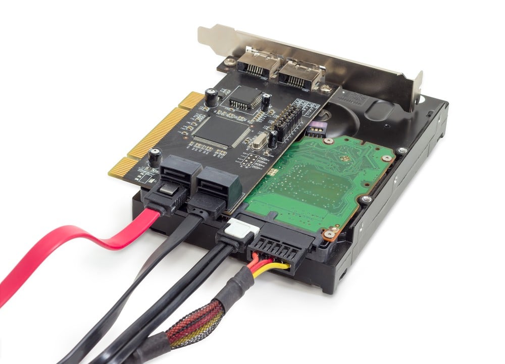
The cables you choose for CAN Bus systems are more than just physical connections; they are the lifelines that carry critical information. To ensure reliable communication, selecting the right type of cable is paramount. The environment in which the cables will operate is a decisive factor. For instance, cables used in high-temperature areas of an aircraft must withstand significant stress without losing performance.
Additionally, the flexibility of the cable is fundamental. Wiring in automobiles, where space is at a premium, requires cables that bend without breaking, maintaining integrity while conforming to the spaces available. The idea is to choose a cable that does not compromise on flexibility, durability, or performance.
But the robustness of a cable is about more than just the immediate environment. It must also resist electronic interference that can disrupt signals. A cable with adequate shielding counters possible noise form surrounding electronics, ensuring that the communication on your CAN Bus network remains clear and uninterrupted.
Ensuring Correct Terminal Resistance for Optimizing CAN Bus Performance
Terminal resistance in CAN Bus wiring isn’t just another specification; it’s a cornerstone of system performance. The ideal resistance ensures signals are pristine by the time they reach their destination. A common benchmark is 120 ohms, balancing cable impedance across the network and keeping reflections to a minimum.
The placement of these resistors can affect performance. Each end of the network harbors a resistor, ensuring signals don’t echo back into the system. This careful consideration keeps the data flowing smoothly, a prime concern where a split-second delay can mean the difference between routine operations and system failures.
Balancing resistance is an art; too much of it and your signals weaken. Too little and the network becomes susceptible to noise. Crafting an environment where resistors work harmoniously requires precision, a deep understanding of the network’s design, and an appreciation for the collaboration between hardware components.
Master the Art of Proper Cable Shielding in CAN Bus Wiring
Cable shielding in CAN Bus wiring is akin to an art form. More than just wrapping a cable, it’s about ensuring the integrity of the data being transferred. Like a guarded fortress, shielding protects the signal within from the electronic disturbances that rage outside.
Choosing a shield entail understanding potential interferences. The humming electronics of a car or the dynamic environment of an aircraft are teeming with electronic noise which can invade and corrupt communication. Your shield must rise to this challenge, providing sanctuary for the delicate signals within.
Yet, a shield is not simply a barrier; it must balance protection with flexibility. Cables must navigate the tight confines and bends of machines and vehicles. The right shielding bends without breaking, integrates without adding undue weight, and protects without compromise.
Utilize Twisted-Pair Cables for Minimizing Interference in CAN Bus Networks
Twisted-pair cables are a smart choice for reducing interference in CAN Bus systems. By intertwining the wires, these cables naturally counteract the noise that might otherwise infiltrate the system. This design cleverly uses the physics of electrical interference to the system’s advantage, effectively canceling many potential disturbances.
What makes twisted-pair cables particularly appealing is their simplicity. The concept is straightforward, yet the benefits are significant. They make it possible to maintain clear communication even in areas thick with electronic activities, such as under a car’s hood or within an aircraft’s fuselage.
The choice between shielded and unshielded twisted-pair cables depends on the specific needs of your installation. While shielding offers added protection against interference, the basic twisted-pair design, in some situations, provides sufficient defense, marrying simplicity with effectiveness.
Paying Attention to Node Positioning for Efficient CAN Bus Topology
Node positioning within a CAN Bus system greatly influences its efficiency. The layout must facilitate clear and direct communication between nodes, avoiding configurations that might introduce signal reflections or losses. A linear topology, with nodes arranged in a deliberate sequence, often yields the best performance, allowing signals to travel smoothly across the network.
Avoid placing nodes in a manner that creates a loop within the network. Loops can confuse signal paths and introduce errors into the system. Keeping the arrangement straightforward ensures that each message reaches its destination without unnecessary detours or complications.
The distance between nodes also deserves careful consideration. Too much distance can weaken signals, while too little can lead to signal crowding. Striking the right balance ensures that each part of the system communicates effectively with minimal signal degradation or loss risk.
Accessibility is another factor that benefits from foresight during node placement. Ideally, nodes should be situated where they can be easily accessed for maintenance or troubleshooting. This consideration can save significant time and effort, ensuring the system remains robust and responsive.
Implement Good Grounding Practices to Stabilize CAN Bus Installations
Grounding in CAN Bus installations is not just a safety measure; it’s a stabilizing force for the entire system. A well-grounded system is less susceptible to electrical noise and interference, which are common culprits behind erratic CAN Bus behavior. Proper grounding provides a reference point for the entire system, helping maintain signal integrity even in electrically noisy environments.
The goal is to achieve a low-resistance connection to the earth, creating a path for any potential interference to be harmlessly dissipated. However, over-grounding can lead to its problems, such as ground loops, which might introduce interference. A single, well-thought-out grounding point often offers the best balance, minimizing potential pitfalls.
Embracing the Future of CAN Bus Technology Solutions
With the clear vision of the future, Sital Technology incorporates CAN Bus technology solutions into the most demanding sectors. We provide bespoke solutions tailored to your project’s needs, from Airborne Interface Cards and High-Reliability Components to specialized IP cores.
Connect with us today and, together, let’s redefine technological boundaries.
